Civil 3D – Part Builder Context Solution Part 2
Part Builder Context Solution Part 1
Ok, at last, the end of the journey. We covered getting the model values out of an existing part. The remaining issue lies with what to do now that we have a mandatory context added to the structure type. Each time we create a new form of that structure type, that variable will be added to the Part XML file with all the other OEM required variables, such as "SHBTh". This would not be a problem except that we still cannot get our non-OEM variables forced into the part model parameters.
As you may recall from earlier discussions, adding an existing catalog parameter to the model parameters is verboten. Consequently without some assistance, each new part would require yet another context parameter to be created in the list. Eventually the list of copies of the same variables would be ridiculous.
What we did figure out is that we can link a required context parameter that is created in the part XML, to a parameter we used in the model parameters.
The basic outline is as follows:
- Create the new part, using the proper structure type.
- Validate the part and save it.
- Create the model to its completion, adding any model parameters as needed.
- Configure the Required Context Parameter to be a range or a list as desired.
- Save the part and exit.
- Edit the Part XML, and change the MODEL parameter’s equation to equal the Required Context Parameter.
- Save the file and perform a catalog regen, and a catalog validation.
- Check the part validation file to confirm all is well. If it says there is a duplicate parameter, return to the Part XML, find the parameter definition that is a duplicate, and delete it so that only one parameter definition remains
Civil 3D – Part Builder Context Solution Part 1
I stated previously that David Neill gave me an idea. A simple switch that had not been useful previously. The problem was that I had just not returned to it after so many new ideas. Thanks David!! I guess collaboration works huh.
It took a while. I had beaten this up over and over. I did not want to rerun it all. Through the frustration, I just kept thinking there is no way David is crazy. Eventually, I got the combination right.
This article proceeds with the premise that everyone is familiar with part builder to some degree, and has an existing part that needs to be made variable. If not, I have a load of info already to use to catch up.
I did say multi part. Don’t worry, there are only 2 parts. The first is what David ad I worked to beat, and the second is when that wasn’t good enough for me.
Part 1 – Getting our existing Parameters into structure that allows later adjustments.
Part 2 – Getting the Catalog require parameters BACK INTO the model.
I have rewritten this 3 times. Please forgive me if it is a bit shabby. It is all starting to run together now.
The old problem
We have been fighting an old issue of customizable parameters. We can make he basic parameters such a height, width, etc. adjustable in the Civil 3D environment, but not specific feature parameters that we need. Say like the angle of a structure slope. After working so hard on a structure, who wants to be stuck with a limitation. David and I did get some ranges and lists to come through, but we couldn’t do it on a consistent basis…until now.
I will go through and identify the major portions of this adjustment. As I do I will discuss the issues, and explain the edits. We will be changing things as we go. This is not a tutorial, but more of an explanation, and a few warnings that have not been made clear elsewhere.
We will focus on the following:
- Some basic information about the Catalog
- Getting into the Part Builder Catalog in 2010
- The Custom Switch
- The Model Variables
- The Context
- The Named Parameter
- The thing that hides Successes and Failures the most
- Validation
Civil 3D – Revised Part Builder News
Ok, whew! We did it. After weeks of rework the custom parameters have been introduced and now stay put! We have ranges and lists without error.
We….
I say we, because my new associate, David Neill, was working it at the same time. He suggested reintroducing an old issue into the new arrangement of edits. He was right.
David is the moderator of the LinkedIn site Civil 3D Part Builder. He discusses these problems and many more. If you are not part of the group, check it out. http://www.linkedin.com/groups?gid=1789091&trk=myg_ugrp_ovr
Autodesk
As many of you know I have been trying to get some input from the big dogs on this. Indications were pointing to some poor bastard over there was being asked to answer a couple simple questions on my behalf. While some of the conversations I had left me with the impression that Autodesk was employing the “is it worth our time?” evaluation, the official settlement is that they don’t have the ability to assist.
The teams that were involved in that phase of the development have redistributed an in many cases have been laid off. I know both of these issues to be absolutely true, not only in Civil, but in Manufacturing as well.
Is it worth their time? I don’t think so. Really. One popular professional said, “Insert a block an get on with it”. After spending hundreds of hours pouring over these issues and answering questions, I agree. Do I use the parts, Yes. I already have them built. I continue to build them for people for a fee. However I still see very efficient designs using null structures every day.
Will they fix it in revision one day. I think so. But it may wait for a an architecture overhaul. I really have no idea.
There are so few using that part of the software, that our pleas for help are often not heard. I have stated that rather than address it, they simply ignore it. I can’t say that since I have been replied to about the issues. What I can say is that commenting on the blogs is not enough. You have a VAR, use them. Who knows, they may comp you a year of subscription to get off their back. Hmmm….
Autodesk has called the hand, and well it’s a push. They can’t help, but David and I will show you what we can to get it going.
So…..
I will explain the issues. After that, if you need detailed help, you can email me. Perhaps we can work something out.
Revision
This post was revised. There was some contention that certain statements were not true. Information I gathered indicated otherwise, but in the end, I cannot prove beyond a doubt hat I was not lied to. Therefore this revision will correct a possible error. An apology will follow in another post so that it will not be overlooked.
Civil 3D – Part Builder Part 7
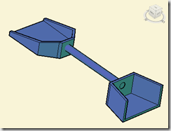
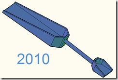
In the last session we created the Structures in the Civil 3D environment. In this session we will modify the configuration to add the slopes to a list, in order to change the structure to be consistent with the corridor side slope.
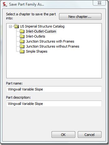
Open up Wingwall Sloped in Part Builder. Since we have something that hopefully works, let’s save a new part. This way we have both. “If it aint broke, then don’t try and fix it”. Let’s try Wingwall Variable Slope.
Pick the ‘Save As’ button on the toolbar. The ‘Save Part Family As…’ dialog will appear allowing us to change the Chapter, Part Name, and Part Description. Leave the chapter as Inlet-Outlet-Custom, cut change the Name and Description to Wingwall Variable Slope.
Hit OK.
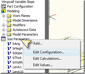
Right Click Size parameters and select Edit Configuration.
Civil 3D – Part Builder Part 6
Backup your model
Before we begin, I seriously and strenuously suggest you back up your model. Don’t do the saveas (which is fine I suppose), but instead use Windows explorer to copy the .DWG and .XML files to a backup location. The VISTA path to these items is C:\ProgramData\Autodesk\C3D 2009\enu\Pipes Catalog\US Imperial Structures\Inlet-Outlet-Custom\
Map the User Parameters to the Application
You may remember the parameters that were handed down when we verified the structure a few sessions ago. These ‘handed down’ parameters are those that the application uses in it’s controls, and were assigned when we used the Part Configuration Undefined Bounding Shape. Without these, the structure cannot be modified. These parameters are SHBTh, SHBW, and SVPC, which are the Thickness, Base Width, and the Vertical Pipe Clearance respectively. We used the user parameters (like bThick) to buffer our equations from the application controls, and to make it easier to understand when reading the parameter list. When we go back to make changes, we can disconnect the application parameters, and toy with our user parameters, and then attach them when we are done.
Let’s set these values before we proceed farther. Edit the Model Parameters as follows:
SHBTh = 6
SHBW = 24
SVPC = 24
Now we have given something solid to these values, we can map these to the user parameters we created.
bThick = SHBTh
bWidth = SHBW
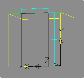
Now that the parameters have been set, we need to change the bounding shape to be a box. Right now, the application will only display the structure as a 3D solid, and many styles will not display
this. To simplify your model in some cases, we need the bounding shape to be a box.
Civil 3D – Part Builder Part 5
Ok, it’s been awhile. Everyone knows I am studying for the test, but I feel so bad for all the people who have been emailing me about the series. I will run through the ‘Homework’, and then complete the configuration session soon hereafter.
Homework Review
We left off with your homework, which was to transfer the Toe plane out, and complete the transitions. I’ll recap it as I run through.
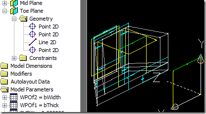
Create the Toe Plane, Offset from the Right Plane a distance of ‘(bHeight-bThick)*bSlope’. Insert the Anchors.
Don’t forget the model parameters for the offset distances.
Civil 3D – Part Builder Part 4
We will pick up where we left off from Part Builder Part 3.
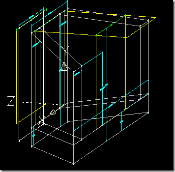
Open our saved part “Wingwall sloped” from the last session. Adjust the view so that you have something similar to the following image:
It’s time to speed things up a bit, so as I refer to procedures, I will once again detail them, and thereafter I will just state that it needs to be completed.
Note: Halfway through I realized some changes needed to be made, in order for this process not to be more confusing than it might already appear. If I missed any odd things in the images, or got out of sync with the variable names, please notify me, and I’ll do my best to correct them.
In this session we will create another offset plane, and additional profiles and transitions. Before we do, it would be prudent to create the remaining profiles that will be referenced to our (current) Right Plane. These will be the locations that the extending walls project into, the “tie in” points. You should be fairly familiar with the basic procedures, Lord knows you’ve had tons of time to practice since my last post, we will pick up the speed a bit. Continue reading
Civil 3D – Part Builder Part 3
We will pick up where we left off from Part Builder Part 2.
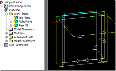
Open our saved part “Wingwall sloped” from the last session. The image below should be representative of what we had before.
Model Parameters
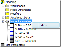
The Model Parameters are the nuts and bolts variables that control the size of the part. The parameters are either dimensions or offsets that are controlling the size and angle of features, or parameters that the user has defined. Expand the collection heading, and you should be able to see all the parameters stored in the part, as well as the values currently assigned. Lets create some user defined parameters to help us in our equations.
Right click on the Model Parameters collection, and select ‘Edit…’
The Model Parameters dialog will appear, allowing changes, additions, and deletions to the existing parameters. On the right you will see buttons, all of which are self explanatory, with the exception of the ‘Calculator…’ button. This allows you to pull variables form a list (without having to remember and type them), and evaluate the result of a proposed equation. Any time you need to map a parameter to another, you can use this feature instead of typing if you wish. Continue reading
-
Archives
- March 2010 (2)
- February 2010 (5)
- January 2010 (5)
- December 2009 (3)
- November 2009 (5)
- October 2009 (8)
- September 2009 (11)
- August 2009 (5)
- July 2009 (4)
- June 2009 (4)
- May 2009 (4)
- April 2009 (7)
-
Categories
-
RSS
Entries RSS
Comments RSS

Civil 3D – Part Builder Comments Please
Ok, Part Builder is not easy. Evan with a tutorial and a workflow, it’s still not easy.
There is at least 1 person in the community that has had trouble with the series outcome. I need to know how everyone did.
Good, Bad, and otherwise. Please offer us your comments.
If there is a bug in the procedure, I need to get it fixed for everyone else.
January 30, 2009 Posted by John Evans | 2009, Part Builder | Autodesk, Civil 3D 2009, comments, Part Builder, Problem, tutorial | 12 Comments